Nov 04, 2019 General tolerance ISO 2768 does not specify where to use these tolerances. Tolerance class is defined as per design requirements and manufacturing capability. For example: for sheet metal parts ISO 2768–mk is used. And for machined components ISO 2768–fh can be used. ISO 2768-2: 1989, General tolerances — Part 2. Machining Tolerances Calculator (limits and fits) Fig 1. Machining Tolerances. In order to ensure that any machined shaft and mating hole fit exactly as required, irrespective of where and how. ISO 2768-1:1989(en). Part 2: Geometrical tolerances for features without individual tolerance indications. ISO 8015: 1985, Technical drawings?
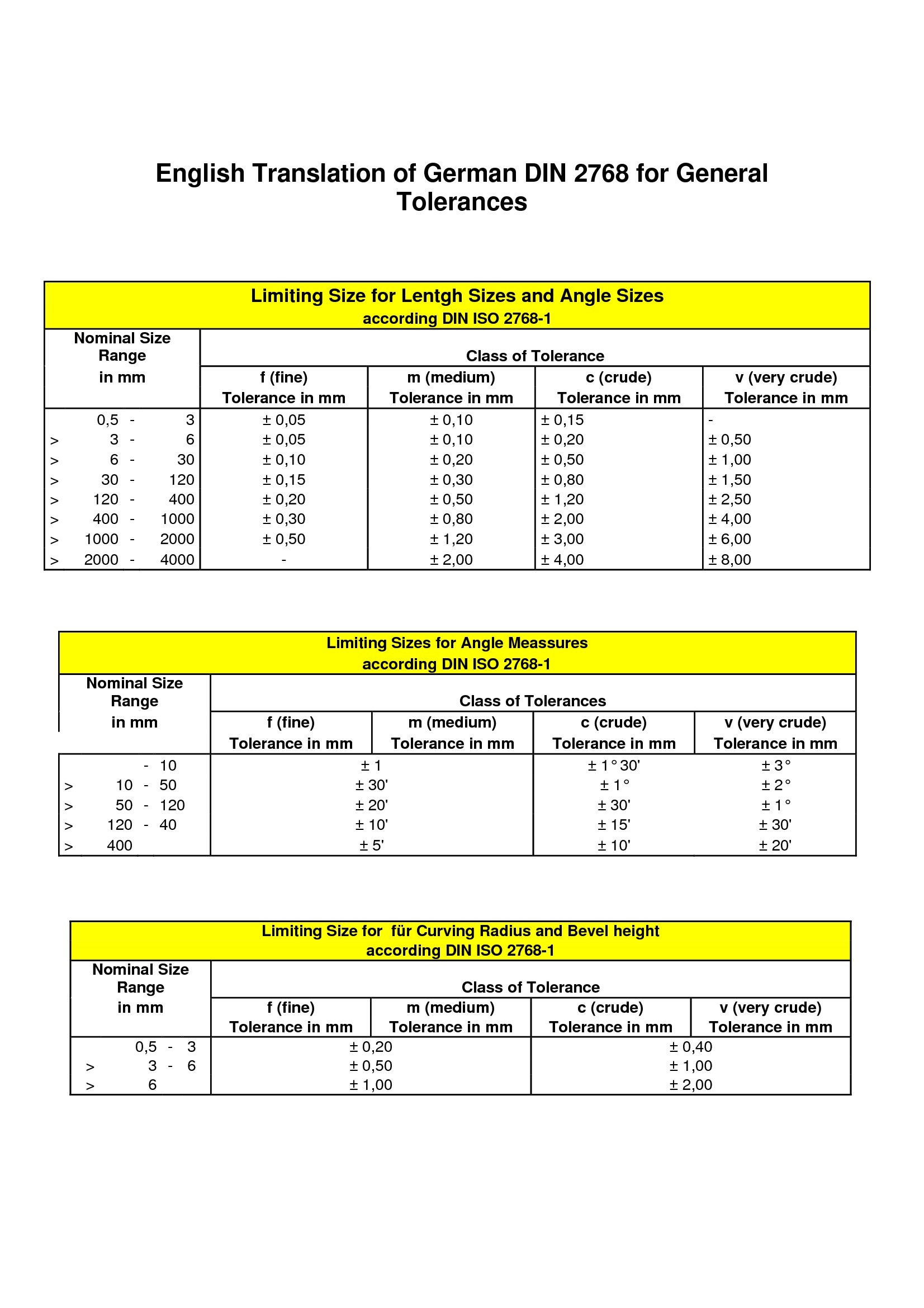
According to DIN ISO 2768-1
'ISO 2768 invokes a set of general tolerances based on a study of common machine shop practices. If the part does not meet these general tolerances, the part might still be accepted if it seems to work in its' function. Sep 12, 2011 - The system of tolerances and fits ISO can be applied in tolerances. Hint: For hole tolerances, tolerance zones H7, H8, H9 and H11 are used preferably. H11/h11, H11/h9 Slipping fits of parts with great tolerances. ISO 2768-1: General tolerances for linear and angular dimensions without.
According to DIN ISO 2768-2
General tolerances for linear measures and level squares with four tolerance classes are useful for simplifying drawings.
By choosing the tolerance class precision levels common in workshops should be taken into account.
Iso 2768 Hole Tolerances - Nitrosociety
If smaller tolerances are needed or bigger ones are more economical,
then these tolerances are indicated next to the nominal size.
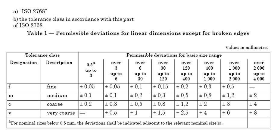
Tabular 1 Limits for linear measures
| Tolerance- class | Limits in mm for nominal sizes in mm | |||||||
0,5 to 3 | above | above 6 to 30 | above 30 to 120 | above 120 to 400 | above 400 | above 1000 | above 2000 | |
| f (fine) | ± 0,05 | ± 0,05 | ± 0,1 | ± 0,15 | ± 0,2 | ± 0,3 | ± 0,5 | - |
| m (medium) | ± 0,1 | ± 0,1 | ± 0,2 | ± 0,3 | ± 0,5 | ± 0,8 | ± 1,2 | ± 2 |
| c (coarse) | ± 0,15 | ± 0,2 | ± 0,5 | ± 0,8 | ± 1,2 | ± 2 | ± 3 | ± 4 |
| v (very coarce grob) | - | ± 0,5 | ± 1 | ± 1,5 | ± 2,5 | ± 4 | ± 6 | ± 8 |
For nominal sizes below 0,5 mm the limit measures are to be indicated directly at the nominal measure.

Tabular 2 Limit measures for radius of curvature and chamfer height
| Tolerance class | Limits in mm for nominal sizes in mm | ||
0,5 to 3 | above 3 to 6 | above 6 | |
| f (finne) | ± 0,2 | ± 0,5 | ± 1 |
| m (medium) | |||
| c (coarse) | ± 0,4 | ± 1 | ± 2 |
| v (very coarse) | |||

Bei Nennmassen unter 0,5 mm sind die Grenzabmasse direkt am Nennmass anzugeben.
Tabelle 3 Grenzabmasse für Winkelmasse
| Tolerance class | Limits in mm for nominal sizes in mm | ||||
to 10 | above 10 to 50 | above 50 to 120 | above 50 to 400 | above 400 | |
| f (fine) | ± 1 ° | ± 30 ' | ± 20 ' | ± 10 ' | ± 5 ' |
| m (medium) | |||||
| c (coarse ) | ± 1 ° 30 ' | ± 1 ° | ± 30 ' | ± 15 ' | ± 10 ' |
| v (very coarce) | ± 3 ° | ± 2 ° | ± 1 ° | ± 30 ' | ± 20 ' |
For nominal sizes below 0,5 mm the limit measures are to be indicated directly at the nominal measure. If general tolerances according to ISO 2768-1 are valid,
the following has to be inserted in the title box, i.e. for tolerance class medium
ISO 2768 – m or general tolerance ISO 2768 – m
For new designs only the general tolerance according to DIN ISO 2768-1 should be valid. The limit measurements of the tolerance classes m and f of DIN ISO 2768-1 are identic with those of DIN 7168-1.
Iso 2768 Hole Tolerance

According to DIN ISO 2768-2
DIN ISO 2768-2 is for simplifying drawing and fixes general tolerances in three tolerance classes for form and position.
By choosing a special tolerance class exactly the precision level common in workshops should be taken into account.
Iso 2768 Hole Tolerances - Wondersupernal
If smaller tolerances are needed or bigger are more economical these tolerances should be mentioned directly according to ISO 1101.
General tolerances for form and position should be used while the tolerance principle according. to ISO 8015 is valid and while this is mentioned in the drawing.
This tolerance principles says that no opposite relation between measure, form and position tolerance exists (principle of superposition).
See Full List On Ramo.se
| Tolerance class | General tolerances for straightness and evenness in mm | |||||
Range of specified size in mm | ||||||
to 10 | above 10 to 30 | above 30 to 100 | above 100 to 300 | above 300 to 1000 | above 1000 to 3000 | |
H | 0,02 | 0,05 | 0,1 | 0,2 | 0,3 | 0,4 |
K | 0,05 | 0,1 | 0,2 | 0,4 | 0,6 | 0,8 |
L | 0,1 | 0,2 | 0,4 | 0,8 | 1,2 | 1,6 |
| Tolerance class | General tolerances for straightness and evenness in mm | |||||
Range of specified size in mm | ||||||
to 100 | above 100 to 300 | above 300 to 1000 | above 1000 to 3000 | |||
H | 0,2 | 0,3 | 0,4 | 0,5 | ||
K | 0,4 | 0,6 | 0,8 | 1 | ||
L | 0,6 | 1 | 1,5 | 2 | ||
| Tolerance class | General tolerances for symmetry | |||||
Range of specified size in mm | ||||||
to 100 | above 100 to 300 | above 300 to 1000 | above 1000 to 3000 | |||
H | 0,5 | |||||
K | 0,6 | 0,8 | 1 | |||
L | 0,6 | 1 | 1,5 | 2 | ||
Iso 2768 Hole Tolerances

General tolerances for form and position are valid for form elements for which form and position tolerances are not indicated individually.
They are applicable for all characteristics of the form elements accept cylinders, profiles of any line or surfaces, inclines, coaxiality, position and total movement.
General ISO Geometrical Tolerances Per. ISO 2768 | GD&T ...
Ramo AB ansvarar ej för eventuella felaktigheter i ovanstående information.
Ramo AB takes no responsibility in the eventuality of errors in the above information.