= 10.62kW Hence wattmeter 1 reads 10.62kW From Equation (1), wattmeter 2 reads (12−10.62)=1.38kW. Three loads, each of resistance 30, are connected in star to a 415 V, 3-phase supply. Determine (a) the system phase voltage, (b) the phase current and (c) the line current. A ‘415 V, 3-phase supply’ means that 415 V is the line voltage, VL. Download PDF - Polyphase Circuits qn85xrq80kn1. This is a non-profit website to share the knowledge. To maintain this website, we need your help. GE POLYPHASE WATTMETER Fig. 4 - Wiring schematic of lamp and metering circuit Individual voltages and currents obtained from additional;hunts and transformers can be recorded during a run to detect line voltage changes or lanmp changes. No changes were observed. The lamp power P(E) is then P(E) = scale reading X 80.93 kW. The un-certainty is. 34434B Meter Description. Polyphase 34434b 1902 Westinghouse Pat. Great condition, the latch works, comes with the instruction manual with serial number, original meter connections chart, hand drawn charts from the 1930s and some of the original cables that have become a little brittle from age. Date and a first calibration date of the leather.

Problems
1.The input power to a 3-phase a.c. motor is measured as 5kW. If the voltage and current to the motor are 400V and 8.6A respectively, determine the power factor of the system?
Power P=5000W,
line voltage VL = 400 V,
line current, IL = 8.6A and
power, P =√3 VLIL cos φ
Hence
power factor = cosφ=P√3VLIL
=5000 √3 (400) (8.6)
=0.839
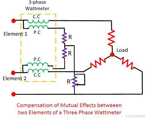
2.Two wattmeters are connected to measure the input power to a balanced 3-phase load by the two-wattmeter method. If the instrument readings are 8kW and 4kW, determine (a) the total power input and (b) the load power factor.
(a)Total input power,
P=P1 +P2 =8+4=12kW
(b) tan φ =√3(P1 − P2)/(P1 + P2)
=√3 (8 – 4) / (8 + 4)
=√3 (4/12)
=√3(1/3)
= 1/ √3
Hence φ= tan−1 1 √3 =30◦
Power factor= cos φ= cos 30◦ =0.866
3.Two wattmeters connected to a 3-phase motor indicate the total power input to be 12kW. The power factor is 0.6. Determine the readings of each wattmeter.
If the two wattmeters indicate P1 and P2 respectively
Then P1 + P2 = 12kW | ---(1) |
tan φ =√3(P1 − P2)/(P1 + P2)
And power factor=0.6= cos φ.
Angle φ= cos−10.6=53.13◦ and
tan 53.13◦ =1.3333.
Hence
1.3333 =√3(P1 − P2)/12
From which,
P1 − P2 = 12(1.3333) /√3
i.e. P1 −P2 =9.237kW ----(2)
Adding Equations (1) and (2) gives:
2P1 = 21.237
i.e P1 = 21.237/2
= 10.62kW Hence wattmeter 1 reads 10.62kW From Equation (1), wattmeter 2 reads
(12−10.62)=1.38kW
4.Three loads, each of resistance 30, are connected in star to a 415 V, 3-phase supply. Determine
(a) the system phase voltage, (b) the phase current and (c) the line current.
A ‘415 V, 3-phase supply’ means that 415 V is the line voltage, VL
(a) For a star connection, VL =√3Vp Hence phase voltage, Vp = VL/√3
=415 /√3
=239.6 V or 240 V
correct to 3 significant figures
(b) Phase current, Ip = Vp/Rp
=240/30
=8 A
(c)For a star connection, Ip = IL Hence the line current, IL = 8 A
5.Three identical coils, each of resistance 10ohm and inductance 42mH are connected (a) in star and (b) in delta to a 415V, 50 Hz, 3-phase supply. Determine the total power dissipated in each case.
(a) Star connection
Inductive reactance,
XL =2πf L =2π (50) (42×10−3) =13.19
Phase impedance,
Zp =√(R2+XL2)

=√(102 +13.192) =16.55
Line voltage, VL =415 V
And phase voltage,
VP =VL/√3=415/√3=240 V.

Phase current,
Ip =Vp/Zp =240/16.55=14.50 A. Line current,
IL =Ip =14.50 A.
Power factor= cos φ=Rp/Zp =10/16.55 =0.6042 lagging.
Power dissipated,
P =√3VLIL cosφ=√3 (415) (14.50)(0.6042) =6.3kW(Alternatively,
P =3I2R=3(14.50)2(10)=6.3kW)
(b) Delta connection
VL = Vp = 415 V,
Zp = 16.55_, cos φ = 0.6042lagging (from above). Phase current,
Ip =Vp/Zp =415/16.55=25.08A. Line current,
IL =√3Ip =√3(25.08)=43.44A.
Power dissipated,
P =√3VLIL cosφ
=√3 (415)(43.44)(0.6042) = 18.87kW
(Alternatively,
P =3I2R
=3(25.08)2(10) =18.87 kW)
6.A 415V, 3-phase a.c. motor has a power output of 12.75kW and operates at a power factor of 0.77 lagging and with an efficiency of 85 per cent. If the motor is delta-connected, determine (a) the power input, (b) the line current and (c) the phase current.

(a) Efficiency=power output/power input.
Hence
(85/100)=12.750 power input from which, Power input = 12. 750 × 10085
=15 000W or 15Kw
(b)Power, P=√3 VLIL cos φ, hence
Polyphase Wattmeter Pdf File
(c)line current,
IL = P/ √3 (415)(0.77)
=15 000/ √3 (415) (0.77)
=27.10A
(d)For a delta connection, IL =√3 Ip,
Hence
Phase current,Ip = IL/√3
=27.10 /√3
=15.65A
7.A 400V, 3-phase star connected alternator supplies a delta-connected load, each phase of which has a resistance of 30_ and inductive reactance 40_. Calculate (a) the current supplied by the alternator and (b) the output power and the kVA of the alternator, neglecting losses in the line between the alternator and load.
A circuit diagram of the alternator and load is shown in Fig.
(a) Considering the load:
Phase current, Ip =Vp/Zp
Vp =VL for a delta connection,
Hence Vp =400V.
Phase impedance,
Zp =√ (R2+XL2)
=√ (302 +402) =50
Figure
Hence Ip =Vp/Zp =400/50=8A.
For a delta-connection,
Line current, IL =√3 Ip =√3 (8) =13.86 A.
Polyphase Wattmeter Pdf Download
Hence 13.86A is the current supplied by the alternator.
(b) Alternator output power is equal to the power Dissipated by the load
I.e. P =√3 VLIL cos φ, Where cos φ = Rp/Zp = 30/50 = 0.6.
Hence P =√3 (400) (13.86) (0.6) = 5.76kW.
Alternator output kVA,
S=√3 VLIL =√3 (400) (13.86)
9.60 kVA.
Summary
In the late 1800s, companies that supplied electricity to consumers needed a way to measure how much customers used -- and then charge them accordingly. Paul McGahan, a Westinghouse electrical engineer created a practical polyphase wattmeter in 1899 to measure electric power usage. This design was adopted by other companies and remained a standard well into the mid-1900s.
In the late 1800s, companies that supplied electricity to consumers needed a way to measure how much customers used -- and then charge them accordingly. Paul McGahan, a Westinghouse electrical engineer created a practical polyphase wattmeter in 1899 to measure electric power usage. This design was adopted by other companies and remained a standard well into the mid-1900s.
Date Made

1903-1906
Creators
Place of Creation
Collection Title
On Exhibit
at Henry Ford Museum in Made in America
Object ID
29.1333.16
Credit
Polyphase Wattmeter Pdf Online
From the Collections of The Henry Ford. Gift of Westinghouse Electric and Manufacturing Company.
Polyphase Wattmeter Pdf Free
Material
Metal
Color
Black (Color)
Dimensions
Height: 12 in
Width: 7 in
Length: 4.5 in
Inscriptions
on front:WESTINGHOUSE, ELEC & MFG. CO. / PITTSBURG, PA., U.S.A.POLYPHASE / WATTMETER